LAB 3 ADVANCED VPNS MULTIPOINT GRE TUNNELS
- Dean McKenzie
- Oct 8, 2022
- 3 min read


Next we will be introducing multipoint gre tunnels technologies and it’s advantages over point-to-point gre tunnels in branches and spoke businesses and environments, not to mention campus-to-campus connections. Configure your physical or virtual environment to reflect a similar topology illustrated below:
If you have not had an opportunity to read Lab1 please go back and take a look. This article lacks a lot of the detail that was obtained in lab one and builds on that knowledge.

Within this lab we will be configuring Multipoint GRE Tunnel between R1-R4; R5 will be acting as an ISP Router.
Configuring the Routers with the following addresses in the table below.
Hostname | IP Addresses |
R1 | LoopBacks: Lo0: 10.1.1.0/24 Lo1: 10.1.2.0.24 Physical Interfaces: Gig0/0: 192.1.10.1 |
R2 | LoopBacks: Lo0: 10.2.1.0/24 Lo1: 10.2.2.0.24 Physical Interfaces: Gig0/1: 192.1.20.1LoopBacks: Lo0: 10.2.1.0/24 Lo1: 10.2.2.0.24 Physical Interfaces: Gig0/1: 192.1.20.1 |
R3 | LoopBacks: Lo0: 10.3.1.0/24 Lo1: 10.3.2.0.24 Physical Interfaces: Gig0/2: 192.1.30.1 |
R4 | LoopBacks: Lo0: 10.4.1.0/24 Lo1: 10.4.2.0.24 Physical Interfaces: Gig0/1: 192.1.40 |
R5 (ISP Router) | Physical Interfaces: Gig0/0: 192.1.10.5 Gig0/1: 192.1.20.5 Gig0/2: 192.1.30.5 Gig0/3: 192.1.40.5 |
Lab Tasks

Task 1
Configure MultiPoint GRE Tunnel between R1-R4, using the 192.168.10/24 address block, with the last octet being the same as the Router number; Once completed we will configure Next Hop Resolution Protocol Mappings.
Configure the mGRE tunnel and NHRP with the following parameters located in the table.
NHRP Settings | Tunnel Settings |
NHRP ID - 1234 | Tunnel Authentication Key 1234 |
NHRP Authentication Key - cisco | ######################## |
######################## | ######################## |
######################## | ######################## |
Configurations
R1:

int tunnel 1
 ip address 192.168.1.1 255.255.255.0
 ip nhrp network-id 1234
 ip nhrp authentication cisco
 tunnel source 192.1.10.1
 tunnel mode gre multipoint
 tunnel key 1234
R2:

int tunnel 1
 ip address 192.168.1.2 255.255.255.0
 ip nhrp network-id 1234
 ip nhrp authentication cisco
 tunnel source 192.1.20.2
 tunnel mode gre multipoint
 tunnel key 1234
R3:
int tunnel 1
ip address 192.168.1.3 255.255.255.0
ip nhrp network-id 1234
ip nhrp authentication cisco
tunnel source 192.1.30.3
tunnel mode gre multipoint
tunnel key 1234R4:
int tunnel 1
ip address 192.168.1.4 255.255.255.0
ip nhrp network-id 1234
ip nhrp authentication cisco
tunnel source 192.1.40.1
tunnel mode gre multipoint
tunnel key 1234At this point you can attempt to ping the new tunnel interfaces we just created however the ping will be unsuccessful due to the lack of NHRP mappings.

Task 2
In order for unicast traffic to work lets add the NHRP mappings to our tunnel interfaces, from R1-R4 and as we are going to be performing dynamic routing we also need to add multicasting for EIGRP to work. Configure multicast so that all routers point to R1 as the routing hub.
R1:

int tunnel 1
 ip nhrp map 192.168.1.2 192.1.20.2
 ip nhrp map 192.168.1.3 192.1.30.3
 ip nhrp map 192.168.1.4 192.1.40.4

R2:

int tunnel 1
 ip nhrp map 192.168.1.1 192.1.10.1
 ip nhrp map 192.168.1.3 192.1.30.3
 ip nhrp map 192.168.1.4 192.1.40.4

R3:

int tunnel 1
 ip nhrp map 192.168.1.1 192.1.10.1
 ip nhrp map 192.168.1.2 192.1.20.2
 ip nhrp map 192.168.1.4 192.1.40.4

R4:

int tunnel 1
 ip nhrp map 192.168.1.1 192.1.10.1
 ip nhrp map 192.168.1.2 192.1.20.2
 ip nhrp map 192.168.1.3 192.1.30.3
Task 3
Configure EIGRP with the autonomous system id of a value of 1234, allowing to route the private loopback networks through the mGRE tunnel.
Disable split-horizon on R1 to allow routes to propagate from the spoke routers to the other spoke routers, failing to disabling split-horizon on the next hop server or R1 in our case will prevent other spoke routers in our topology from learning the private loopback networks.
To disable split-horizon use the following command on R1 only! The user will experience the EIGRP neighbors reestablishing.
R1:
int tunnel 1
no ip split-horizon eigrp 1234
Proof is in the pudding!
Verify & Testing
Confirm that you can see and reach the private loopback networks, from any spoke router. R2-R4.

We can see that all the private loopback networks have been populated dynamically in the global routing table, next we will test reachability from R2-R4.
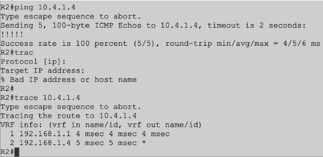
From our last reachability test we use the trace command, from the output one can see that traffic is first going toward the hub, R1 in this case and then going to R4 the packets final destination. This concludes lab three, mGRE lab.


Comments